

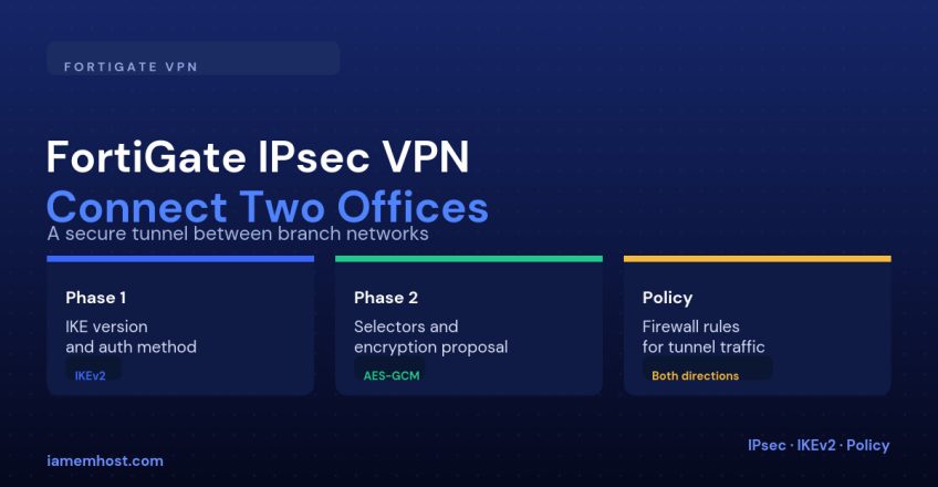

Connecting two offices behind FortiGate firewalls is one of the most common enterprise VPN scenarios, and FortiOS’s VPN Creation Wizard handles most of the tedium — but it’s still worth understanding what it’s actually configuring underneath, especially when the tunnel comes up but traffic still doesn’t pass, which is almost always a firewall policy or routing gap rather than an IPsec problem.
What You Need From Both Sides First
| Item | Example |
|---|---|
| Public IP of each FortiGate (or DDNS if dynamic) | 203.0.113.10 and 198.51.100.20 |
| LAN subnet behind each FortiGate | 10.1.0.0/24 and 10.2.0.0/24 — must not overlap |
| A shared pre-shared key or certificates | Agreed out-of-band before configuration begins |
Step 1: Run the VPN Creation Wizard
VPN > IPsec Wizard > Name: HQ-to-Branch
  Template: Site to Site > FortiGate
  Remote Device: IP Address
  IP Address: 198.51.100.20
  Outgoing Interface: wan1
  Authentication Method: Pre-shared Key
  Local Interface: lan
  Local Subnets: 10.1.0.0/24
  Remote Subnets: 10.2.0.0/24
The wizard creates the Phase 1 and Phase 2 configuration, a static route toward the remote subnet, and address objects for both LANs — but it does not reliably create every firewall policy you need, so verify those manually.
Step 2: Confirm Phase 1/Phase 2 Proposals Match the Remote Side
VPN > IPsec Tunnels > edit tunnel > Phase 1 Proposal
  IKE Version: 2
  Encryption: AES256, Authentication: SHA256
  DH Group: 14

  Phase 2 Selectors
  Encryption: AES256, Authentication: SHA256
  Enable Perfect Forward Secrecy (PFS): DH Group 14
Both FortiGates need identical Phase 1 and Phase 2 proposals — if the other end is a different vendor’s firewall, this is where mismatches most often surface, since “AES256/SHA256/DH14” needs to be spelled out the same way on both sides even if the GUIs look different.
Step 3: Firewall Policies in Both Directions
IPsec tunnels in FortiOS appear as virtual interfaces, and need explicit policies just like any other interface pair — one for each direction of traffic:
Policy & Objects > Firewall Policy > Create New
  Name: LAN-to-VPN
  Incoming Interface: lan
  Outgoing Interface: HQ-to-Branch (the IPsec tunnel interface)
  Source: 10.1.0.0/24
  Destination: 10.2.0.0/24
  Action: ACCEPT

# And the mirror policy:
  Name: VPN-to-LAN
  Incoming Interface: HQ-to-Branch
  Outgoing Interface: lan
  Source: 10.2.0.0/24
  Destination: 10.1.0.0/24
  Action: ACCEPT
Step 4: Confirm Routing
The wizard usually adds a static route automatically, but verify it exists and points out the tunnel interface, not a physical one:
Network > Static Routes
  Destination: 10.2.0.0/24
  Interface: HQ-to-Branch
Troubleshooting
| Symptom | Likely cause |
|---|---|
| Tunnel shows down in VPN > IPsec Monitor | Phase 1 proposal mismatch, or wrong public IP/pre-shared key |
| Tunnel up, but ping fails across sites | Missing firewall policy in one direction, or missing static route |
| Works one direction only | The mirror policy for the return direction wasn’t created |
| Tunnel drops and reconnects repeatedly | Dead Peer Detection settings mismatched, or an upstream NAT device altering UDP 500/4500 traffic |
Conclusion
The wizard gets a FortiGate-to-FortiGate IPsec tunnel most of the way there, but the two things worth checking by hand every time are the firewall policies in both directions and the static route pointing at the tunnel interface — the tunnel itself can show “established” in the monitor while traffic still silently drops because of either one.